WE DO NOT HAVE ANY FURTHER INFORMATION. WE SIMPLY ADD THIS PAGE AS WE GET A LOT OF CALLS FOR AN OLD BUSINESS WE INHERITED THE PHONE NUMBER FROM.
THE OLD BUSINESS KINDLY MADE THIS INFO AVAILABLE FOR THEIR OLD CUSTOMERS.
WE DO NOT KNOW ANYTHING FURTHER ABOUT THIS PRODUCT. SORRY.
FIX SHEET FOR TPI, TPI 2 & D-GAS BLACK SERIES LPG SYSTEM
FOR TURBO CHARGED ENGINES.
This fix removes faulty electronic parts and replaces them with robust mechanical parts that work. Leave the rest of the system as is. Ie the tank, ON / OFF Switch, and Regulator.
Other than the parts noted in this brief, no other parts are required to be changed. Flow will still be controllable via the jets originally supplied and pressure from the regulator. Using the Injector Solenoid below means that contaminated LPG will not affect the system as it has been doing as the orifice in the NEW Injector Solenoid is much bigger than the orifice in the original Injector Solenoid.
________________________________________________________________________________________________
For NON TURBO ENGINES you need to purchase a Frequency to Analog Converter from Ocean Controls.
Click here for more information
________________________________________________________________________________________________
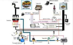
Original Wiring Schematic
 (Click image to enlarge)
The premise of this instruction is to remove from the aforementioned systems the sometimes troublesome ECU and Driver Board which currently drives the system. Leave the Converter/Regulator and all parts UP stream of this as is.
LETS GET STARTED:
The original LPG ECU will have an orange wire that is attached to an engine run signal: Either the alternator “W” Wire or diesel pump. This Orange purple wire is the wire you will use to trip the relay discussed below.
Identify the Orange Wire and remove this wire from the LPG system’s electronics … not the vehicle. The rest of the harness, LPG ECU, Driver Board and Injector can be removed/disconnected and thrown away.
The original Injector Solenoid will be replaced by a Lock Off Solenoid. I will call this part the “Injector Solenoid” from this point on for simplicity.
Lock Off Injector Solenoid:

The existing Purple Wire identifies engine running. Use the Purple Wire to energise an Apexus Safety Cut Out Relay (discussed later) that supplies battery power to a new Injector Solenoid which will now act as the new Injector.
Injector Solenoid can be purchased here: https://www.airod.com.au/main_files/solenoidvalves.htm
(Remember they would call it a “LPG Lock Off Valve”)
Apexus Safety Cut Out Relay

Using a Safety Cut Out Relay from Apexus, Model CO103 connects to a fused battery 12v positive to the Supply Terminal. The output terminal of the Apexus CO103 Safety Cut Out Relay is then connected to a HOBB Switch. The Apexus CO103 Safety Cut Out Relay is grounded to the vehicle chassis via the mounting tab. The Green Wire from the Apexus CO103 Safety Cut Out Relay connects to the Purple Wire.
Apexus can be contacted here: https://www.apexus.com.au/
The Purple Wire acts as a trigger. When engine is running the Purple Wire will energise the relay and allow battery power to run to the Injector Solenoid via the Hobb Switch.
Hobb / Pressure Switch


The Hobb Switch is used to allow the Injector Solenoid to energise only when the Pressure Switch “sees” some turbo boost. You would set the Hobb Switch to somewhere around 3-5 PSI depending on your vehicle and when you want the LPG System to start “gassing”.
The Hobb Switch will act as a switch for the Injector Solenoid. When turbo is boosting to, say, 4 psi, the Hobb Switch closes its contacts and allows the Injector Solenoid to open and pass LPG into the engine.
The gas pressure increases with turbo pressure via the boost line going to the convertor on the existing system.
Hobb Switches can be purchased here: (https://www.atpturbo.com/mm5/merchant.mvc?Screen=PROD&Product_Code=ATP-BCS-003&Category_Code=BCS)
To re-iterate: To turn ON the Injector Solenoid you use the Hobb Switch to power it up. The Hobb Switch will be set to around 4 PSI and when the turbo boosts to that pressure the Hobb switch (normally open) will close and make contact and energise the Injector Solenoid.
NB: I would normally use “normally open” so that the boost triggers the Hobb Switch to close and provide continuity. This will allow the lock off solenoid to have continuity and activate, thus allowing gas to flow.
If by mistake you purchase a normally closed Hobb Switch you will require a relay that is “tripped” to power “ON” when the Hobb Switch trips.
TUNING:
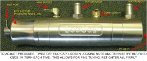
You need to achieve 20 – 25% LPG to Diesel ratio. You adjust gas ratio by jetting and pressure. To begin the LPG Convertor/Regulator should be set to provide a base pressure of 14 PSI (1 Bar). The Gross Tuning to achieve 20 – 25% gas / diesel ratio is achieved by the jets. Fine Tuning can be made by adjusting the Regulator pressure UP or DOWN for MORE or LESS LPG.
SETTING BASE PRESSURE

Clockwise increases pressure.
PIC OF ORIGINAL REGULATOR

WE DO NOT HAVE ANY FURTHER INFORMATION. WE SIMPLY ADD THIS PAGE AS WE GET A LOT OF CALLS FOR AN OLD BUSINESS WE INHERITED THE PHONE NUMBER FROM.
THE OLD BUSINESS KINDLY MADE THIS INFO AVAILABLE FOR THEIR OLD CUSTOMERS.
WE DO NOT KNOW ANYTHING FURTHER ABOUT THIS PRODUCT. SORRY.
